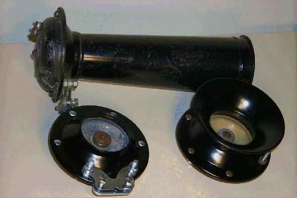
Figure 1. Illustration of three Auto-Lite horns.
I have compiled some notes on the Auto-Lite Corporation horns used in the Dodge 3/4 ton 4×4 trucks built during World War II. My interest arose since my late model WC-52 has a twelve volt system while other earlier models were six volt systems. These horns were made by the Electric Auto-Lite Corporation in Toledo, Ohio. The ordnance supply catalog SNL G-502 lists two horns: the AL-HD-4001 for the carryall and command vehicles, and the AL-HA-4001 for the weapons carrier, gun motor carriage, ambulance, telephone maintenance and installation emergency repair chassis vehicles. The AL-HD-4001 is a 12 volt horn with Chrysler part number CC-641198 and the AL-HA-4001 is a 6 volt horn with Chrysler part number CC-635446. Note that the ordnance supply catalog lists the weapons carrier as a 6 volt vehicle. 12 volt vehicles were available later in the war to better accommodate radio gear.
Another reference identifying the horn models is ordnance supply catalog SNL G-657, which lists several truck models as shown in Table 1.
| Year and Engineering Symbol | 6 Volt | 12 Volt |
|---|---|---|
| 1940-T202 | 683367 | 683372 |
| 1940-T203 | 683367 | Not Used |
| 1940-T207 | 683367 | 683372 |
| 1940-T211 | 683367 | 683372 |
| 1940-T215 | 683367 | 683372 |
| 1940-T112 | 683367 | Not Used |
| 1940-T118 | 683367 | Not Used |
| 1940-T118 | 635446 | Not Used |
| 1940-T214 | 635446 | 641198 |
| 1940-T223 | 635446 | Not Used |
For the T118 trucks, horn CC-683367 was used up to serial number 81,334,245 and horn CC-635446 after serial number 81,334,245.
Also, Dodge VC-1 – WC-64KD, 1940–1945 by Emile Becker and Guy Dentzer cites two horn styles for the trucks. One style had a long cone length for the 1942–43 period and the other style essentially had no cone for the 1944–45 period. Figure 1 illustrates three Auto-Lite horns with different cone lengths. The horns are all stamped with their voltage rating. The two horns with cones shown are 6 volt horns and the horn with no cone is a 12 volt horn.
Figure 1. Illustration of three Auto-Lite horns.
All the cones have stampings where the coil is located indicating the voltage of the horn and the manufacturer. The short cone and no cone horns have additional markings around the flange. The short cone (6 volt) has: 15-, AUTO LITE MADE IN USA, HA 4033; and the no cone horn (12 volt) has: 46-4, AUTO LITE MADE IN USA, HD 4017B.
Figure 2 illustrates the parts for the 12 volt horn. The six volt horn with a short cone has the same parts except that the coil winding is different (wire size only). Figures 3 through 5 are closeups illustrating the details. The gaskets shown in Figure 2 are new gaskets and Figure 6 illustrates a scaled drawing of the gasket. The inner and outer gasket diameters are 2.03 and 2.46 inches, respectively. The 6 holes for bolts are .25 inches in diameter and are located on a 2.25 inch bolt circle. The notch in the gasket is aligned so that a drainage hole on the cone side of the horn is over the notched region. The long cone has four holes spaced 90 degrees apart while the other two cones have only one hole.
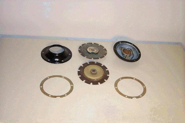
Figure 2. The parts for the 12 volt horn. A second diaphragm has been included to show the other side.
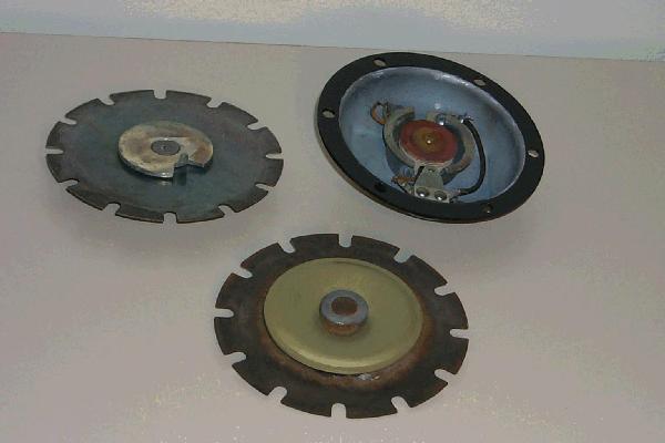
Figure 3. Closeup of the diaphragms and 12 volt coil.
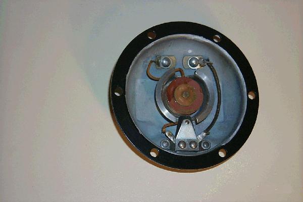
Figure 4. Closeup of the 12 volt coil.
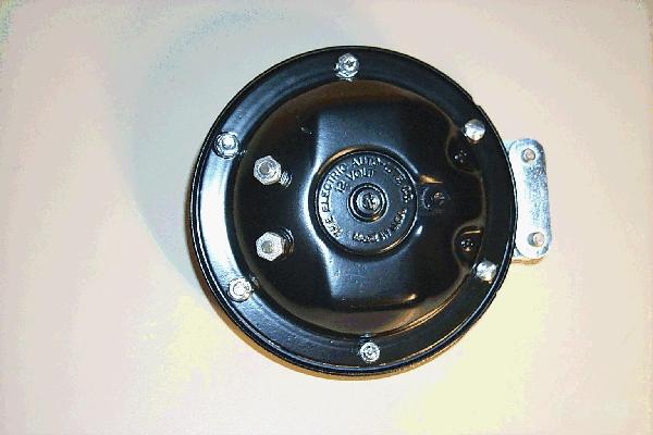
Figure 5. Closeup of the back side of the horn (coil part).
Figure 6. The gasket outline. Click to open PDF.
The DC resistance for the two voltage coils was determined by measuring the voltage drop across and current through the coils. The 6 volt coil resistance was approximately .195 ohms and the 12 volt coil resistance was approximately .5 ohms. The wire diameters for the 6 and 12 volt coils were 47 mil (17 gauge) and 33 mil (20 gauge), respectively. Using the resistance values, wire diameter and the conductivity for copper, the wire lengths for the 6 and 12 volt coils are approximately 41.6 and 52.6 feet, respectively.
My WC-52 is a late model vehicle (June 1945) and I have noticed an additional component in the horn circuit not described in the 1942 technical manual. Mounted on the firewall is a bi-metal circuit breaker connected in series to the horn from the starter side of the circuit. The markings on the thermostat are: Klixon, CDA 15, Spencer Thermostat Co. This 15 amp device is still available and the package looks identical.
Examination of the horn indicates how it works. When the horn button is pressed, voltage is applied to the coil. The coil generates a magnetic field which pulls the diaphragm to the coil. Note the iron puck on the diaphragm — the additional iron may assist the diaphragm in being drawn to the coil when energized. When the diaphragm is drawn in to the coil, the tab on the diaphragm mechanically opens a contact which breaks the circuit and stops current flow in the coil. Once current flow stops, the diaphragm returns to its original position. The contact then closes again to allow current to flow. The diaphragm continues this repetitive motion which moves the air in an oscillatory manner to produce the horn sound.