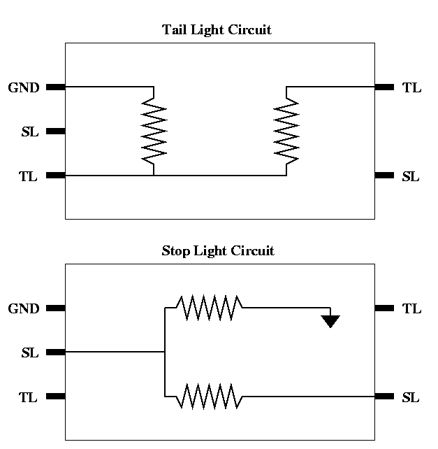
Figure 1. The electrical schematic for the voltage converter box. Click to open PDF.
During the final stages of my WC-52 renovation, I became aware that very little information was available for the wiring between a 6 volt and 12 volt electrical system. In particular, the voltage converter mounted at the rear left bottom of the cargo box drew my attention. I replaced all the wiring harnesses with new reproduction harnesses. The new harnesses fit very well and were well made. All was fine until I tried to connect the voltage converter in the electrical system to supply 6 volts to the trailer connector. The harness supplying voltage to the converter had three wires bundled together but the converter had only two terminals on the inner (input) side. The converter did have three terminals on the outward side, from which a short three-wire harness went to the trailer connector.
Looking at available literature such as TM 9-808, all voltage references are 6 volt, which is not surprising since 12 volt electrical systems did not appear until later in WW II. It was important to maintain the 6 volt supply at the trailer connector for backward compatibility. In a 6 volt system, the three wires going to the trailer connector are for the stop light (green/black), tail light (blue), and ground (green).
The harness bundle which feeds the converter box was taped together with all wires having the same free length. This would be fine if going directly to the trailer connector. However the inner side terminals on the voltage converter box were stamped ST and TL with no natural, physical way to connect the ground wire. The outward side terminals on the converter box were stamped ST, TL, and GND.
Being an electrical engineer, I examined the voltage converter box and found it to consist of two simple voltage divider networks, each comprised of two wire-wound power resistors. The resistors in each network were of the same value, which made sense since the desired final voltage (6V) was to be half of the input voltage (12V). However, the resistance values between the two networks were slightly different (as well as their physical size), which is not surprising since each supplies a slightly different load.
Figure 1 illustrates the electrical schematic of the voltage converter box. Note that the two voltage divider networks are not electrically connected the same way. The voltage divider ground for the stop light is directly grounded to the box of the converter, while the voltage divider ground for the tail light is connected to the ground terminal on the outward side of the voltage converter. It is interesting to note that the two voltage divider networks derive their ground differently. One is through the box of the voltage converter (and hence through the left side of the cargo box) and the other is through the wiring harness. Note that it is important to properly ground the cargo box in a 12 volt system — each left and right side has its own grounding strap. Additionally, the ground for the tail light voltage divider is achieved by bringing the ground from the trailer connector to the voltage converter.
Figure 1. The electrical schematic for the voltage converter box. Click to open PDF.
With this information, I contacted the vendor of the reproduction harness to inquire about this discrepancy. He was aware of the 6 and 12 volt electrical systems but had never come across this situation. His template, acquired from another source, did not accommodate any difference between the two voltage configurations. He noted from his experience that the voltage converters were seldom wired in.
From the above information, I concluded that the ground wire should not have been bundled (taped) with the stop and tail light wires as far as it was. I confirmed this through correspondence with Raymond Shumate, who has a WC-51 with a 12 volt electrical system still in its original state. This was also confirmed in a picture of the voltage converter box on page 202 in Dodge VC-1 – WC-64KD, 1940–1945 by Emile Becker and Guy Dentzer.
A picture of the final installation in my vehicle is shown in Figure 2. I hope this information can assist others.
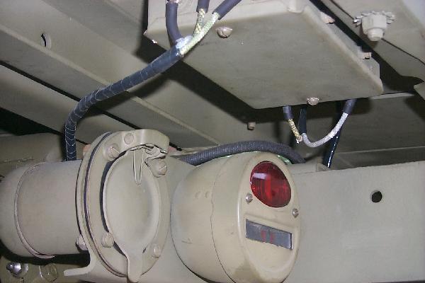
Figure 2. Illustration of wiring for the voltage converter box.