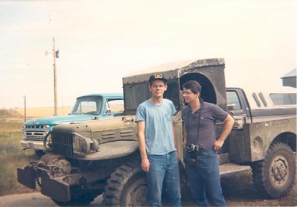
Figure 1. The WC-52 before restoration.
I became aware that little information is available for the cargo box description of late model WC-51/52 vehicles during a frame-up restoration. I was fortunate since the cargo box was in good condition. My vehicle, a WC-52, has been in my family on the family farm in Eastern Montana since the end of WW II. My uncle had acquired it as surplus equipment in an auction at the Tacoma ordinance plant and driven it from there to the farm during the late fall of 1945 on a three-day drive — a warm drive over the Rockies in an open cab.
The weapons carrier began life on the farm as a grain truck. The upper horizontal wood surfaces were covered with tin sheeting to minimize grain loss through any cracks, the tail gate was removed and replaced by one with a sliding gate to allow grain to gravity drain from the cargo box, and the hauling capacity was increased with additional vertical side boards. After a couple of years, a larger 1947 Chevrolet truck with a hydraulic lift was purchased to haul grain. Unfortunately, the canvas for the weapons carrier was used to make a canvas top for the newer truck box. The weapons carrier saw only light use afterward. My father had also put a cab top from a Model T on the weapons carrier to make driving in colder weather less of a challenge. Figure 1 illustrates the weapons carrier with this arrangement before the restoration.
Figure 1. The WC-52 before restoration.
I am providing information on the cargo box to assist fellow enthusiasts who may not be as fortunate as I was in having a template to follow. Dave Pfeifer performed the mechanical portion of the restoration. Figure 2 illustrates the final restored vehicle. I confirmed many details of my cargo box with another cargo box from a WC-51 manufactured during the same time period, belonging to Raymond Shumate, which has not been restored. As a disclaimer, I do not guarantee the absolute accuracy of the information presented.
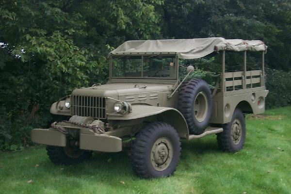
Figure 2. The restored WC-52.
The guidance provided here comprises text, images, and drawings. I have not dimensioned all aspects of the drawings since final dimensions and especially hole locations should be manually confirmed for a particular cargo box. The overall and relative orientation of the various wood components are illustrated in Figures 3 through 5.
Figure 3. Top view of cargo box. Click to open PDF.
Figure 4. Alignment of the left side vertical side board. Click to open PDF.
Figure 5. Alignment of the right side vertical side board. Click to open PDF.
The wood surfaces consist of 3/4" thick white oak boards that were tongue-and-grooved to form wider boards, glued with exterior wood glue. Floor boards are 7/8" thick. The original primer was gray; I used white Zinsser Bulls Eye primer/sealer (two coats), which is thicker but likely a better primer than the original. The wood grain was still visible after two primer coats — sand between coats, especially before the color coat, to ensure dependable adhesion. Biscuits are also a possibility over T&G since after priming and painting one cannot tell the difference.
Two different floor board widths were used. The width of the four inner boards (7.625") was determined by the hole spacing in the cross-sils minus 3/8" to allow spacing for a 5/16" bolt. These four boards had .1" recess edges for the bed strips. The width of the recess accommodated the 1.5" width of the strips. The width of the outer two boards (7.812") made up the remaining floor width. My interior cargo box width is 48.5" and I allowed a .25" clearance gap between the 3/4" vertical side boards. Note that these side boards do not seat on top of the cargo box bed floor but extend to the same surface on which the exterior bed floor boards rest. The outer two bed boards had recessed edges (.1", on the bottom side) to accommodate the cargo box frame and wheel well splash plates, with recess widths of 1.25". All bed floor boards were recessed .1" along the front bottom 1.5" to accommodate a lip from the front cargo box panel. The board lengths are a touch (1/8") under 6 feet to ensure the tail gate does not bind with the boards when in the vertical position. Figures 6 and 7 detail the dimensions.
Figure 6. Floor board dimensions. Click to open PDF.
Figure 7. Floor board cross-sections. Click to open PDF.
Figure 8 illustrates the major dimensions for the vertical side boards. Also shown is a 3/4" thick, 9.5" long wood part used to provide a support surface for the stamped metal battery cover, attached to the vertical side board with three wood screws and two recessed tee-nuts for the battery cover bolts. The splash plate cutouts were made with a router and a jig (Figure 9) to make two cuts: one on a 19.75" arc for a 1/4" groove for the splash plate curved lip recessed into the wood, and a second on an 18.25" arc to separate the sector from the side board. The router bit radius must be accounted for in this cut. The locations of the splash plates were determined by the holes in the corner bed strips. Note that the curved strip of wood between the groove and the curved edge needs to be recessed to allow the splash plate to be flush to the surface of the vertical side boards — two different recessed levels are needed. Finally, the exterior side of the circular edge is beveled. Carbide router bits perform better than standard steel bits with white oak.
Figure 8. Vertical side board dimensions. Click to open PDF.
Figure 9. Illustration of router jig to form the circular cuts in the vertical side boards. Click to open PDF.
All six boards shown in Figures 10 through 13 have cross members to provide additional support, shown in Figure 14. All compartment lids with an open edge are chamfered (1/8"), as is the top inner edge of the wheel well board. The boards which accommodate the front hinge are recessed .1". Boards along the outer edge of the cargo box are recessed 1/8" for a width of 1¼" on the top to be positioned in a pocket of the cargo box. Currently 1/8" spacing is provided between the lids and adjoining pieces; if less is desired, the lids must be made proportionally larger.
Figure 10. Left front compartment lid. Click to open PDF.
Figure 11. Right front compartment lid. Click to open PDF.
Figure 12. Right center wheel well board. Click to open PDF.
Figure 13. Right rear compartment lid. Click to open PDF.
Figure 14. Cross member boards. Click to open PDF.
All four cargo box compartment lids have a similar construction with a 1/4" thick, 1" wide, centered insert at the ends to prevent splitting. The front compartment lids did not have an insert at the hinge side. The lids are roughly 14"×18". The notches for the clasp hardware were cut with a circular saw, 1/4" deep, to form a flat surface 4.5" long.
The two top center boards over the wheel wells have a 1¼" square, 25.5" long support wood piece along the inner wheel well joint. The left side has a metal cable tray; the holes in the cable tray determine the hole positions and the cross member locations. The right side is symmetrical but has no cable tray. Figures 4 and 5 illustrate the alignment particulars.
Several different types of head styles were used on the original beds I have seen. The most common bolt has a step head, similar to carriage bolts but with a thinner head and larger head diameter. Most of the necessary step bolts are still available. What are not available are the bed strips and corner strips — available strips have a wider rolled edge which will not allow a step bolt to seat properly. A carriage bolt head will fit but the appearance is not the same.
The cargo box is attached to the frame with six 1/2" step bolts. The two rear ones are about 9" long and the four front and mid-span ones are about 6" long. About 100 5/16" and 35 1/4" step bolts are required in total.
Step bolt sources:
Hodell-Natco IndustriesThe cargo box floor rested on 6 cross-sils on the frame, with 1/4" Masonite pad (2"×2") spacers. The cross-sil over the gas tank had leather pads with a metal spacer; I replaced those with a pad available from VPW used on M-37 boxes.
A special vibration-resistant washer called a periphery toothed, domed lock washer was used throughout. Roughly 100 are used in a variety of places. They can be obtained from Hodell-Natco Industries (part number DIST0310101OP, Shakerproof part number 4818-16-02). Note that only .062" thick ones are currently available, not the .039" thick ones used in the 1940s.
Other hardware matching the original can be obtained through McMaster Carr and Moore Industrial Hardware. Specifications:
Continuous hinge — McMaster CarrThe listed draw latch only has the latch itself. The strike must be fabricated as shown in Figure 14a.
Figure 14a. Latch strike. Click to open PDF.
The following images illustrate the cargo box from interior views, wheel well views, and under the cargo box floor.
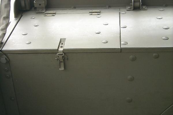
Figure 15. Rear left compartment lid.
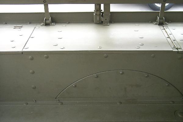
Figure 16. Center left wheel well region.
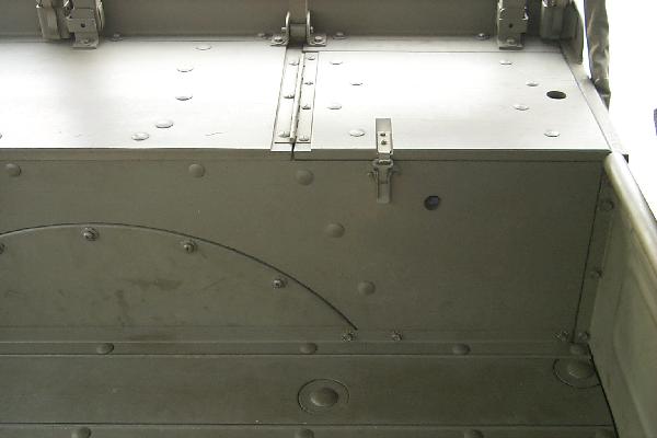
Figure 17. Front left compartment lid.
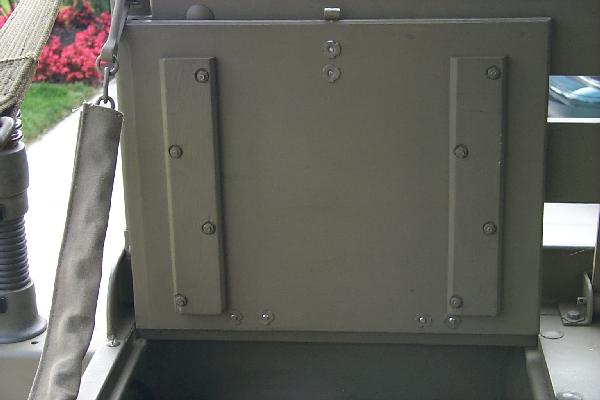
Figure 18. Rear left compartment lid, bottom view.
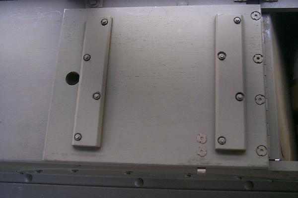
Figure 19. Front left compartment lid, bottom view.
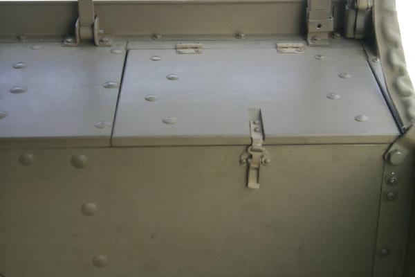
Figure 20. Rear right compartment lid.
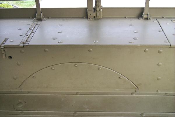
Figure 21. Center right wheel well region.
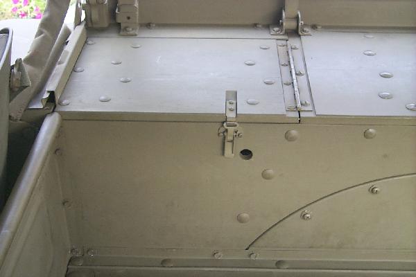
Figure 22. Front right compartment lid.
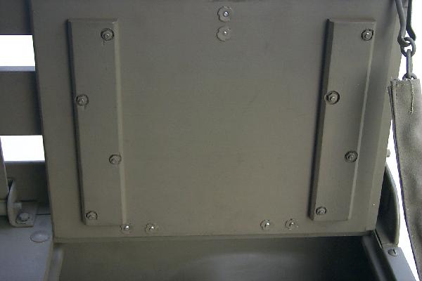
Figure 23. Rear right compartment lid, bottom view.
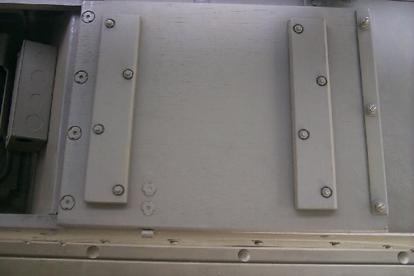
Figure 24. Front right compartment lid, bottom view.
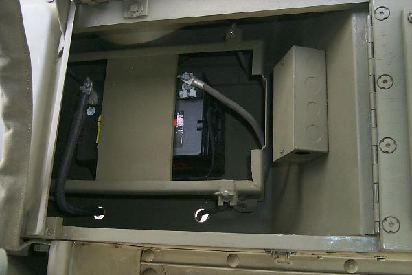
Figure 25. Battery compartment.
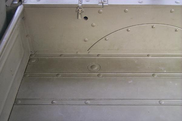
Figure 26. Front right cargo box side.
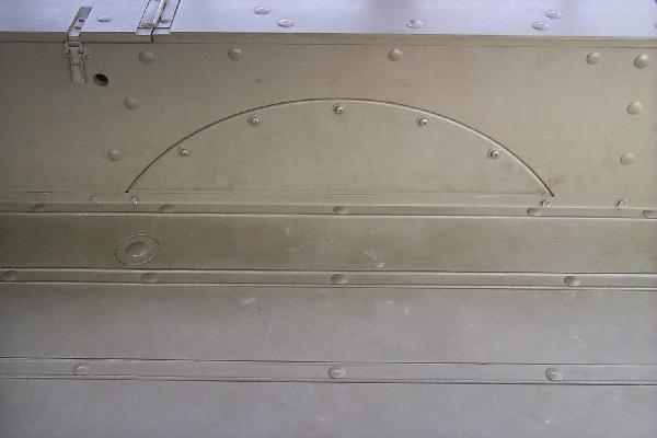
Figure 27. Center right cargo box side.
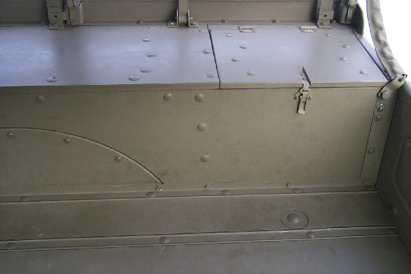
Figure 28. Rear right cargo box side.
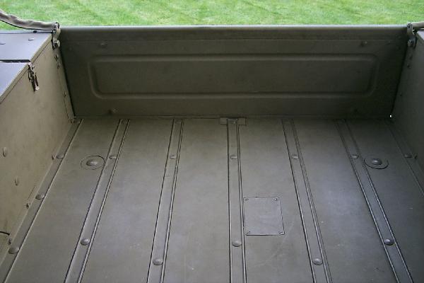
Figure 29. Rear of cargo box floor.
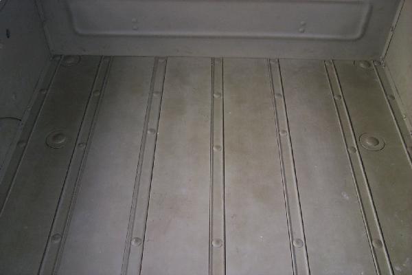
Figure 30. Front of cargo box floor.
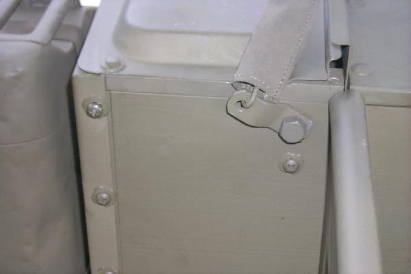
Figure 31. Front right close-up of cargo box side.
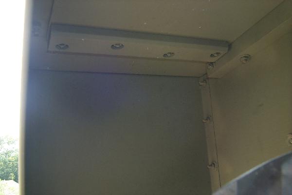
Figure 32. Rear right wheel well.
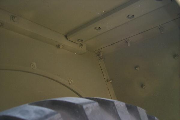
Figure 33. Front right wheel well.
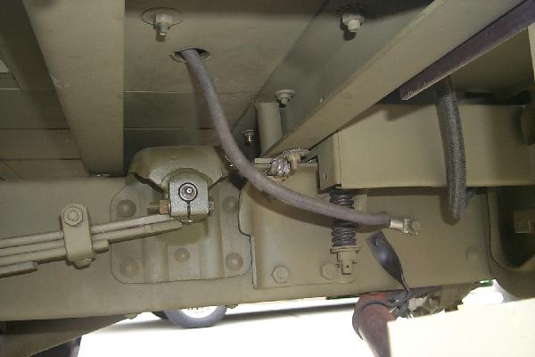
Figure 34. Front right cross-sils.
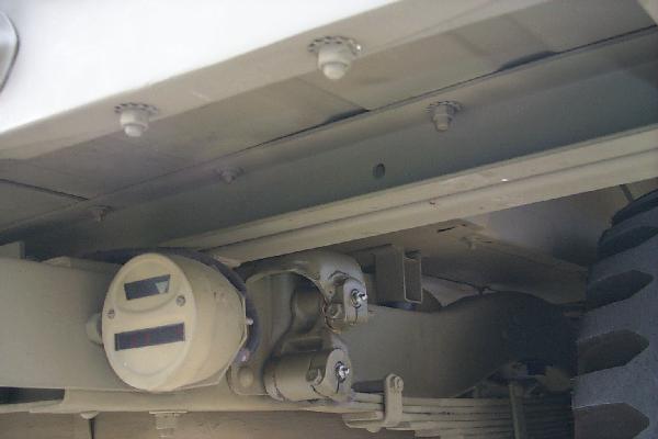
Figure 35. Rear right cross-sils.
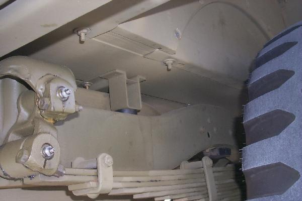
Figure 36. Right gas tank cross-sil.
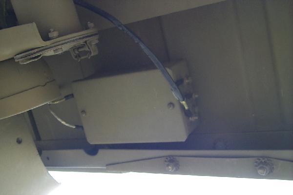
Figure 37. Voltage divider box for 12 volt trailer.
Figure 38. Front left wheel well.
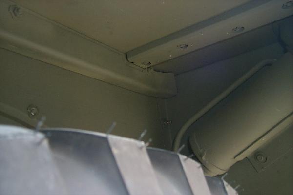
Figure 39. Rear left wheel well.
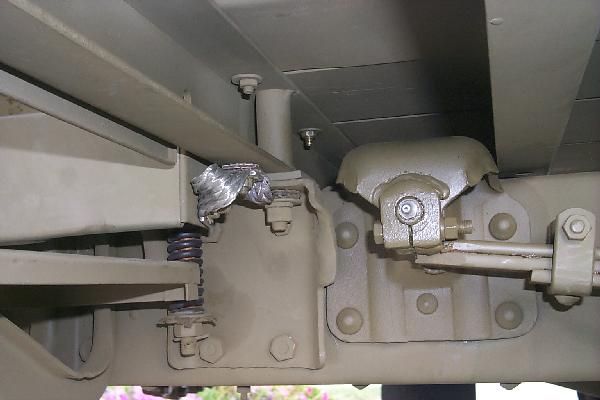
Figure 40. Front left cross-sils.
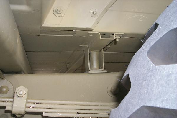
Figure 41. Third left cross-sil.
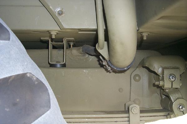
Figure 42. Right gas tank cross-sil.
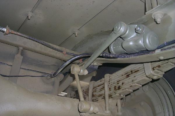
Figure 43. Typical view of cargo floor from underside.
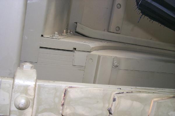
Figure 44. Direct up view of right side wheel well.